Tuesday, July 26, 2011

cmucam

//PIC: PIC16F877A
//Crystal Frequency: 20MHz
//Compiler: HI-TECH ANSI C


#include
#include
__CONFIG(0x3F32);
#define LCD_RS RD0
#define LCD_RW RD1
#define LCD_EN RD2
#define LCD_LIGHT RD3
#define LCD_DATA PORTD //D7-D4
#define LCD_PULSE() ((LCD_EN=1),(LCD_EN=0))
#define BAUD 9600
#define _XTAL_FREQ 20000000

void pic_init(void);
void uart_init(void);
void lcd_init(void);
void lcd_write(unsigned char c);
void lcd_clear(void);
void lcd_goto(unsigned char pos);
void lcd_string(const char *s);
void convert(unsigned int no, char base);
void display(char number);
void uart_transmit(char data);
void uart_string(const char *s);

char mode,cam[40],di[10],z,rec[]={"ACK"};
unsigned int counter[2];

static void interrupt isr(void)
{char i;
if(RCIF==1){
counter[0]=0;
if(RCREG=='T') z=0;
cam[z]=RCREG;
if(z<38) z++;} if(TMR0IF==1){ TMR0IF=0; if(counter[0]<20000) counter[0]++; if(counter[0]==5000) z=0; } } main() {int i,j,space,value[8]; pic_init(); //initialize PIC uart_init(); //initialize UART lcd_init(); //initialize LCD lcd_goto(0x00); //select first line lcd_string(" CMUCAM EXAMPLE "); //display string lcd_goto(0x40); //select second line lcd_string(" "); //display string lcd_goto(0x14); //select third line lcd_string(" "); //display string lcd_goto(0x54); //select fourth line lcd_string(" "); //display string LCD_RS=0; lcd_write(0x40); LCD_RS=1; for(i=0;i<=63;i++) lcd_write(0b00000); mode=0; counter[1]=0; for(;;){ counter[1]++; switch(mode){ case 0:{ if(counter[1]==1){ for(i=0;i<=39;i++) cam[i]=0x20; lcd_goto(0x40); //select second line lcd_string("RS "); //display string uart_string("RS"); uart_transmit(0x0D);} //Enter else if(counter[1]==1000){ counter[1]=0; j=0; for(i=0;i<=2;i++){ if(cam[i]==rec[i]) j++;} if(j==3){ counter[1]=0; mode++;}} lcd_goto(0x14); //select third line LCD_RS=1; for(i=0;i<=19;i++) lcd_write(cam[i]); lcd_goto(0x54); //select fourth line LCD_RS=1; for(i=20;i<=39;i++) lcd_write(cam[i]); break;} case 1:{ if(counter[1]==1){ for(i=0;i<=39;i++) cam[i]=0x20; lcd_goto(0x40); //select second line lcd_string("CR 18 44 "); //display string uart_string("CR"); uart_transmit(0x20); //Space uart_string("18"); uart_transmit(0x20); //Space uart_string("44"); uart_transmit(0x0D);} //Enter else if(counter[1]==1000){ counter[1]=0; j=0; for(i=0;i<=2;i++){ if(cam[i]==rec[i]) j++;} if(j==3){ counter[1]=0; mode++;}} lcd_goto(0x14); //select third line LCD_RS=1; for(i=0;i<=19;i++) lcd_write(cam[i]); lcd_goto(0x54); //select fourth line LCD_RS=1; for(i=20;i<=39;i++) lcd_write(cam[i]); break;} case 2:{ if(counter[1]==1){ for(i=0;i<=39;i++) cam[i]=0x20; lcd_goto(0x40); //select second line lcd_string("TC 0 40 0 40 0 40 "); //display string uart_string("TC"); uart_transmit(0x20); //Space uart_string("0"); uart_transmit(0x20); //Space uart_string("40"); uart_transmit(0x20); //Space uart_string("0"); uart_transmit(0x20); //Space uart_string("40"); uart_transmit(0x20); //Space uart_string("0"); uart_transmit(0x20); //Space uart_string("40"); uart_transmit(0x0D);} //Enter for(i=0;i<=7;i++) value[i]=0; space=0; i=2; do{ if((cam[i]<0x30)|(cam[i]>0x39)) space++;
else value[space]=10*value[space]+cam[i]-0x30;
i++;}
while(space!=8);

lcd_goto(0x14);
lcd_string(" ");
convert(value[0],10);
for(i=2;i>=0;i--) display(di[i]);
lcd_string(" ");
convert(value[1],10);
for(i=2;i>=0;i--) display(di[i]);
lcd_string(" ");
convert(value[2],10);
for(i=2;i>=0;i--) display(di[i]);
lcd_string(" ");
convert(value[3],10);
for(i=2;i>=0;i--) display(di[i]);
lcd_string(" ");

lcd_goto(0x54);
lcd_string(" ");
convert(value[4],10);
for(i=2;i>=0;i--) display(di[i]);
lcd_string(" ");
convert(value[5],10);
for(i=2;i>=0;i--) display(di[i]);
lcd_string(" ");
convert(value[6],10);
for(i=2;i>=0;i--) display(di[i]);
lcd_string(" ");
convert(value[7],10);
for(i=2;i>=0;i--) display(di[i]);
lcd_string(" ");
break;}
default:{
mode=0;
break;}}
}}

void pic_init(void)
{
TRISA=0b00000000;
TRISB=0b00000000;
TRISC=0b10000000;
TRISD=0b00000000;
TRISE=0b00000000;
OPTION=0b00000000;
ADCON1=0b00000110;
INTCON=0b11100000;
PIE1=0b00100000; //Enable RX interrupt
PORTA=0b00000000;
PORTB=0b00000000;
PORTC=0b00000000;
PORTD=0b00000000;
PORTE=0b00000000;
}

void uart_init(void)
{
TXSTA=0b10100100;
RCSTA=0b10010000;
SPBRG=(int)(_XTAL_FREQ/(16.0*BAUD)-1);
}

/* initialise the LCD - put into 4 bit mode */
void lcd_init(void)
{
__delay_ms(15); //delay for LCD Power Up
lcd_write(0x28); //function set
lcd_write(0x0C); //display on/off control
lcd_clear(); //clear screen
lcd_write(0x06); //entry mode set
LCD_LIGHT=1;
}

/* write a byte to the LCD in 4 bit mode */
void lcd_write(unsigned char c)
{
LCD_DATA=(LCD_DATA&0x0F)|(c&0xF0);
LCD_PULSE();
LCD_DATA=(LCD_DATA&0x0F)|((c<<4)&0xF0);
LCD_PULSE();
__delay_us(40);
}

/* clear LCD and goto home */
void lcd_clear(void)
{
LCD_RS=0;
lcd_write(0x1);
__delay_ms(2);
}

/* write a string of chars to the LCD */
void lcd_string(const char *s)
{
LCD_RS=1;
while(*s)
lcd_write(*s++);
}

/* go to the specified position */
void lcd_goto(unsigned char pos)
{
LCD_RS=0;
lcd_write(0x80+pos);
}

void convert(unsigned int no, char base)
{char i;
for(i=0;i<=9;i++) di[i]=0;
i=0;
do{
di[i]=no%base;
no=no/base;
i=i+1;}
while(no!=0);
}

void display(char number)
{switch(number){
case 0:{lcd_string("0");break;}
case 1:{lcd_string("1");break;}
case 2:{lcd_string("2");break;}
case 3:{lcd_string("3");break;}
case 4:{lcd_string("4");break;}
case 5:{lcd_string("5");break;}
case 6:{lcd_string("6");break;}
case 7:{lcd_string("7");break;}
case 8:{lcd_string("8");break;}
case 9:{lcd_string("9");break;}
case 10:{lcd_string("A");break;}
case 11:{lcd_string("B");break;}
case 12:{lcd_string("C");break;}
case 13:{lcd_string("D");break;}
case 14:{lcd_string("E");break;}
case 15:{lcd_string("F");break;}
default:{lcd_string("?");break;}
}}

void uart_transmit(char data){
while(TXIF==0) continue;
TXREG=data;
}

void uart_string(const char *s)
{
while(*s)
uart_transmit(*s++);
}

Wednesday, July 13, 2011

Board Description

You can power the board by USB bus.
The USB can supply 500mA, so there is enough power to drive relays and displays. The microcontroller has a USB port on board . You can drive up to 8 relays and read the status of 8 optocoupler. You can use this inputs for switches, push buttons, or to have a feed back to see if the relays have been effectively switched. The communication protocol between PC and board is very simple, for example, sending the character "6" on the virtual RS232 the first relay will turn on and the board will replay with an "I" character, this response is an acknowledge and makes you sure that the command arrived and was correctly executed.


scheda rele opto

HW description

The board is made of:

  • PCB;
  • microcontroller Microchip (18f2455 -see the Datasheet) with 32 Kb off flash memory, 256 byte of Eeprom memory and controller USB;
  • Optocoupler for input (TPL4N25-4).
  • USB Connector
  • Relays. We can mount two type of relay, one with maximum 30Vcc (or
    125Vac) or another with 230Vac, 2A contact.

Schematics

Schematic USB Board
Fig. 1

Schematic USB Board (2)
Fig. 2

Firmware description

The board firmware receives a command from the PC (using the get function) elaborate the command (by ProcessIO function) and executes the command(toggle the relay or read the input).
This is and example of the source code of the firmware:


void main(void) { /* A7  A6  A5  A4  A3  A2  A1  A0 */ /*    1     1     1     1    1     1     0     0 */ LATA &= 0x0; TRISA &= 0xFC; /* configure port A of uC */ /* B7 B6 B5 B4 B3 B2 B1 B0  */ /*    1   1    1    1   1    1   1    1  */ LATB &= 0x0; TRISB &= 0xFF; /* configure port B of uC */ /* C7 C6 C5 C4 C3 C2 C1 C0 */ /*   0    0    1    1   1    1   0    0 */ LATC &= 0x0; TRISC &= 0x3C; /* configure porta C of uC */ InitializeSystem(); mLED_1_Off();  MSB_num_restart = ReadEEPROM(0x20); LSB_num_restart = RedEEPROM(0x21); if ((MSB_num_restart == 0xFF)&(LSB_num_restart == 0xFF)){   /* blank eeprom */ MSB_num_restart = 0 ; LSB_num_restart = 0 ;  WriteEEPROM ( 0x20, 0); WriteEEPROM ( 0x21, 0); } else {  if (LSB_num_restart == 0xFF){  MSB_num_restart = MSB_num_restart +1; WriteEEPROM ( 0x20, MSB_num_restart); WriteEEPROM ( 0x21, 0); LSB_num_restart = 0; } else {  LSB_num_restart = LSB_num_restart +1; WriteEEPROM ( 0x21, LSB_num_restart); } } EnablePullups();     /* enable pull-up on PORTB */ while(1) { USBTasks();        /*  USB Tasks  */ ProcessIO();        /* See user\user.c & .h */ } } void ProcessIO(void) {    if((usb_device_state < CONFIGURED_STATE)||(UCONbits.SUSPND==1)) return; if(getsUSBUSART(input_buffer,1)){ ... if(input_buffer[0] == '6') /* 0x36 */ { if(mUSBUSARTIsTxTrfReady()){ mRele_1_On();                /* turn on relay number 1*/ putrsUSBUSART("I");    /* acknoledge */ } } ... } }
void main(void) { /* A7 A6 A5 A4 A3 A2 A1 A0 */ /* 1 1 1 1 1 1 0 0 */ LATA &= 0x0; TRISA &= 0xFC; /* configure port A of uC */ /* B7 B6 B5 B4 B3 B2 B1 B0 */ /* 1 1 1 1 1 1 1 1 */ LATB &= 0x0; TRISB &= 0xFF; /* configure port B of uC */ /* C7 C6 C5 C4 C3 C2 C1 C0 */ /* 0 0 1 1 1 1 0 0 */ LATC &= 0x0; TRISC &= 0x3C; /* configure porta C of uC */ InitializeSystem(); mLED_1_Off(); MSB_num_restart = ReadEEPROM(0x20); LSB_num_restart = RedEEPROM(0x21); if ((MSB_num_restart == 0xFF)&(LSB_num_restart == 0xFF)){ /* blank eeprom */ MSB_num_restart = 0 ; LSB_num_restart = 0 ; WriteEEPROM ( 0x20, 0); WriteEEPROM ( 0x21, 0); } else { if (LSB_num_restart == 0xFF){ MSB_num_restart = MSB_num_restart +1; WriteEEPROM ( 0x20, MSB_num_restart); WriteEEPROM ( 0x21, 0); LSB_num_restart = 0; } else { LSB_num_restart = LSB_num_restart +1; WriteEEPROM ( 0x21, LSB_num_restart); } } EnablePullups(); /* enable pull-up on PORTB */ while(1) { USBTasks(); /* USB Tasks */ ProcessIO(); /* See user\user.c & .h */ } } void ProcessIO(void) { if((usb_device_state < CONFIGURED_STATE)||(UCONbits.SUSPND==1)) return; if(getsUSBUSART(input_buffer,1)){ ... if(input_buffer[0] == '6') /* 0x36 */ { if(mUSBUSARTIsTxTrfReady()){ mRele_1_On(); /* turn on relay number 1*/ putrsUSBUSART("I"); /* acknoledge */ } } ... } }

The ProcessIO() function waits for a command. On this example when the board receives the "6" character on virtual RS232 (the USB) the first relay will turn on and answer with "I" character. You can also read how many time the board has been turned on, this counter is saved on the eeprom memory inside the PIC microcontroller.

Software description

Here is an example of software written with Visual Basic. From left ToolBox import the "SerialPort" control. We will use 3 functions of this control, which are: Open, Write, Read

Let's start opening the serial port, with SerialPort.Open.

The SerialPort.Open needs a serial port number to be opened; it is the number
of the virtual serial port (usually it is COM4).
After the virtual serial port is opened, you can send commands using
SerialPort.Write function, for example if you want to turn on the first relay:
SerialPort.Write("6")

To read the answer from the board and to acknowledge the command received
use the SerialPort.Read function

scheda rele visual basic

Command protocol

Send 0 = 0x30 = 48 => Turn on Led and answer  "A" Send 2 = 0x32 = 50 => Turn off Led and answer  "C" Send 5 = 0x35 = 53 => if the puss button is pressed, answer  "G"  otherwise "H" Send 6 = 0x36 = 54 => Turn on Relay 1 and answer  "I" Send 7 = 0x37 = 55 => Turn off Relay 1 and answer  "L" Send 8 = 0x38 = 56 => Turn on Relay 2 and answer  "M" Send 9 = 0x39 = 57 => Turn off Relay 2 and answer  "N" Send a = 0x61 = 97 => Turn on Relay 3 and answer  "O" Send b = 0x62 = 98 => Turn off Relay 3 and answer  "P" Send c = 0x63 = 99 => Turn on Relay 4 and answer  "Q" Send d = 0x64 = 100 => Turn off Relay 4 and answer  "R" Send e = 0x65 = 101 => if input 1 is on, answer  "S" otherwise "T" Send f = 0x66 = 102 => if input 2 is on, answer  "U" otherwise "V" Send g = 0x67 = 103 => if input 3 is on, answer  "W" otherwise "Y" Send h = 0x68 = 104 => if input 4 is on, answer  "J" otherwise "K" Send i = 0x69 = 105 => if input 5 is on, answer  "Z" otherwise "a" Send l = 0x6C = 108 => if input 6 is on, answer  "b" otherwise "c" Send m = 0x6D = 109 => if input 7 is on, answer  "d" otherwise "e" Send n = 0x6E = 110 => if input 8 is on, answer  "f" otherwise "g" Send o = 0x6F = 111 => Turn on Relay 5 and answer  "H" Send p = 0x70 = 112 => Turn off Relay 5 and answer  "B" Send q = 0x71 = 113 => Turn on Relay 6 and answer  "D" Send r = 0x72 = 114 => Turn off Relay 6 and answer  "E" Send s = 0x73 = 115 => Turn on Relay 7 and answer  "F" Send t = 0x74 = 116 => Turn off Relay 7 and answer  "G" Send u = 0x75 = 117 => Turn on Relay 8 and answer  "X" Send v = 0x76 = 118 => Turn off Relay 8 and answer  "m" 

You can also read how many time the board has been powered up:

Send w = 0x77 = 119 => Read the Most significant part of number of restart Send z = 0x7A = 122 => Read the Least significant part of number of restart 
SW_PC_Relay_USB.zip289.38 KB

Wednesday, July 6, 2011

Free Energy


The purpose of this web site is to provide you with an introduction to a series of devices which have been shown to have very interesting properties and some are (incorrectly) described as 'perpetual motion' machines.

What's that you say - perpetual motion is impossible? My, you're a difficult one to please. The electrons in the molecules of rock formations have been spinning steadily for millions of years without stopping - at what point will you agree that they are in perpetual motion?

So, why don't electrons run out of energy and just slow down to a standstill? Quantum Mechanics has shown that the universe is a seething cauldron of energy with particles popping into existence and then dropping out again. If E = mC2, then we can see that a tremendous amount of energy is needed to create any form of matter. Scientists remark that if we could tap even a small part of that energy, then we would have free energy for our lifetime.

The Law of Conservation of Energy is undoubtedly correct when it shows that more energy cannot be taken out of any system than is put into that system. However, that does not mean that we cannot get more energy out of a system than we put into it. A crude example is a solar panel in sunlight. We get electrical power out of the panel but we do not put the sunlight into the panel - the sunlight arrives on its own. This example is simple as we can see the sunlight reaching the solar panel.

If, instead of the solar panel, we had a device which absorbs some of the energy which Quantum Mechanics observes and gives out, say, electrical power, would that be so different? Most people say "yes! - it is impossible!" but this reaction is based on the fact that we cannot see this sea of energy. Should we say that a TV set cannot possibly work because we cannot see a television transmission signal?

Many people have produced devices and ideas for tapping this energy. The energy is often called "Zero-Point Energy" because it is the energy which remains when a system has its temperature lowered to absolute zero. This presentation is introductory information on what has already been achieved in this field: devices which output more power than they require to run. This looks as if they contradict the Law of Conservation of Energy, but they don't, and you can see this when you take the zero-point energy field into account.

The material on this web site describes many different devices, with diagrams, photographs, explanations, pointers to web sites, etc. As some of the devices need an understanding of electronic circuitry, a simple, step-by-step instruction course in electronics is also provided in Chapter 12. This can take someone with no previous knowledge of electronics, to the level where they can read, understand, design and build the type of circuits used with these devices.

This is a very interesting field and the topic is quite absorbing once you get past the "it has to be impossible" attitude. We were once told that it would be impossible to cycle at more than 15 mph as the wind pressure would prevent the cyclist from breathing. Do you want to stay with that type of 'scientific' expert? Have some fun - discover the facts.

There are many, many interesting devices and ideas already on the web. This site does not mention them all by any means. What it does, is take some of what are in my opinion, the most promising and interesting items, group them by category, and attempt to describe them clearly and without too many technical terms. If you are not familiar with electronics, then some items may be difficult to understand. In that case, I suggest that you start with Chapter 12 and go through it in order, moving at whatever speed suits you, before examining the other sections. I hope you enjoy what you read.


Note: When you have finished reading any of the sections shown below, use the 'Back' button of your browser to return to this page. You will need Version 7.0 or later of the Adobe 'Acrobat' reader to display these sections. It can be downloaded free from: here


THE INFORMATION PRESENTED ON THIS WEB SITE IS FOR INFORMATION PURPOSES ONLY. SHOULD YOU DECIDE TO PERFORM EXPERIMENTS OR CONSTRUCT ANY DEVICE, YOU DO SO WHOLLY ON YOUR OWN RESPONSIBILITY -- NEITHER THE COMPANY HOSTING THIS WEB SITE, NOR THE SITE DESIGNER ARE IN ANY WAY RESPONSIBLE FOR YOUR ACTIONS OR ANY RESULTING LOSS OR DAMAGE OF ANY DESCRIPTION, SHOULD ANY OCCUR AS A RESULT OF WHAT YOU DO.


The main information on this web site has been gathered together into a standard book format. You can download the main set of information, including the patents, as an eBook, using this link eBook Release 18.6. The document contains some 2,200 pages and has a file size of about 32 Mb which means that it will take some time to download. It is also possible to use a background download from fileFactory. Alternatively, you can pick individual chapters as you wish. May I suggest that you store anything you download on your local drive as web sites do not remain in place for ever. The last few updates to this document are listed here.


Contents eBook Index: An explanation of the background followed by a general index, an index of devices and an index of the people and devices mentioned. HTML


Introduction Newcomer's Introduction
: A quick guide to what Free-Energy is all about, explaining the basics.
HTML


Chapter 1 Magnet Power: The Wang magnet motor, the Ecklin-Brown motor-generator, Howard Johnson's magnet motor, the 'Carousel' magnet motor, Robert Tracy's magnet motor, Ben Teal's electromagnetic motor, the Jines magnet motor, Stephen Kundel's magnet motor, Charles Flynn's magnet motor, the Steorn magnetic device, George Soukup's magnet motor, Dietmar Hohl's magnet motor, the Muammer Yildiz magnet motor patent, Steele Braden's magnetic track, Emil Hartman's magnetic track, Howard Johnson's magnetic track, the shielded twin-rotor idea, Don Kelly's magnet motor patent and Mike Brady's 'Perendev' Magnet Motor. size 1.0 Mb, 14 Mar 2011 HTML


Chapter 2 Moving Pulsed Systems: The Adams motor/generator, the Phemax self-powered motor/generator, Raymond Kromrey's No-drag Generator, Teruo Kawai's motor, self-powered 800 watt generator, the Muller motor, the RotoVerter, Raoul Hatem's free-energy rotor system, Phil Wood's energy pick-up, Phil Wood's DC motor RotoVerter modification, the David Kousoulides energy pick-up system, Mark Wesling's five-rotor generator concept and Art Porter's magnetic motor system. size 1.3 Mb, 6 Jan 2011 HTML


Chapter 3 Motionless Pulsed Systems: Graham Gunderson's Solid-state Electric Generator, Charles Flynn's magnetic power enhancement system, Lawrence Tseung's magnetic frame, Thane Hines' dual toroid magnetic frame, Dietmar Wehr's Y-frame motionless generator idea, the Annis/Eberly Motionless Generator, the Richard Willis COP>1 generator, TheGuru2You's self-powered electrical generator, Floyd Sweet's VTA, Dan Davidson's acoustic generator, the Pavel Imris optical amplifier, Michael Ognyanov's self-powered power pack, the Meyer-Mace Isotopic Generator, the Colman/Seddon-Gilliespie generator, Hans Coler's passive device, Don Smith's "Resonance Energy Methods", Kwang-jeek Lee's power amplification system, Tariel Kapaladze's self-powered electrical generator, Meguer Kalfaian's Electron-spin power generator and Stan Meyer's Particle Generator patent. size 1.9 Mb, 6 May 2011 HTML


Chapter 4 Gravitational Pulsed Systems: Lawrence Tseung's pulsed wheel, Lawrence Tseung's Impact gravity wheel, Chas Campbell's pulsed flywheel, John Bedini's pulsed flywheel, James Hardy's water-jet generator, the Magnetic Pendulum, Jerzy Zbikowski's Chain Drive, Gravitational Effects, Mikhail Dmitriev's gravity wheel, the Dale Simpson gravity wheel, the Veljko Milkovic pendulum/lever system, the Dale Simpson hinged-plate system, Amr Al-Hossary's gravity wheel and the Murilo Luciano gravity chain. size 1 Mb, 21 Mar 2011 HTML


Chapter 5 Energy-Tapping Pulsed Systems: Frank Prentice's electrical power accumulator, Dave Lawton's cold electricity water-splitter cell, John Bedini's pulsed battery charger, the Tesla Switch, Dave Lawton's cold electricity lightbulb, Bob Boyce's COP=12 energy tapping toroid, Don Smith's devices, Steven Mark's TPU, a Nikola Tesla patent, the Ed Gray power tube, Radiant Energy waves, Nikola Tesla's experiments, Don Smith information, the Alberto Molina-Martinez generator, Alfred Hubbard's device, Joseph Cater's device, Floyd Sweet's VTA, Rosemary Ainslie's heater design, Joseph H. Cater's self-powered generator and Dr Oleg Gritskevitch's 1.5 MW generator. size 1 Mb, 17 Jun 2011 HTML


Chapter 6 Battery-Charging Pulsed Systems:
John Bedini's pulsed systems, battery information from Ronald Knight, Ron Pugh's battery charger build, a self-charging battery pulser, the fan pulse charger, the automotive pulse charger, the self-charging motor, the Alexkor battery charger, the one-battery pulse charger and the Tesla Switch. size 841 Kb, 9 Mar 2011 HTML


Chapter 7 Aerial Systems:
Nikola Tesla's Aerial Plate System, a recent replication of Tesla's Aerial Plate System, Thomas Henry Moray's system, Moray King's circuit suggestions, Hermann Plauston's systems, Roy Meyer's device, Raymond Phillips' RF to DC aerial system and the 'Alexkor' aerial system. size 342 Kb, 9 Mar 2011 HTML


Chapter 8 Fuel-less Engines: The energy in air, Bob Teal's compressed air engine, Scott Robertson's thoughts on putting low-pressure air into a tank of high-pressure air, the Leroy Rogers compressed-air vehicle engine adaption, the Vortex Tube, the Eber Van Valkinberg compressed fluids engine, the Clem engine, Vortex analysis by Prof. Evert, the Josef Papp engine, the Robert Britt engine, the Michael Eskeli turbines, the water-jet generator and the Cahill / Scott generator. size 474 Kb, 17 Jun 2011 HTML


Chapter 9 Passive Systems:
Hans Coler's device, Thomas Trawoeger's pyramid, Karel Drbal's pyramid, James Brock's pyramids, Verne Cameron's pyramid transmission technique, the Pancake coil, Peter Grandic's patent, Les Brown's pyramid information, Joseph Cater's explanation of how all pyramids work, Pier Ighina's passive energy devices, the Joe Cell, Bill Williams' design and recent analytical advances, co-ax cable electrets and Joseph H. Cater's free-energy box. size 1.1 Mb 17 Jun 2011 HTML


Chapter 10 Vehicle Systems: The HydroStar and HydroGen designs, running an engine on water alone, Hydroxy Boosters, electrolyser design, the 'Hogg' electrolyser, Pulse Width Modulation current control, Dave Lawton's replication of Stan Meyer's Water Fuel Cell water-splitter, Dave Lawton's circuits and construction details, pipe-tuning details, Dr Cramton's low-power water-splitting, Stan Meyer's water injection system, Peter Lowrie's hydroxy system, mpg improvement through cam timing, the Firestorm spark plug, Ted Ewert's Vortex Turbine, Water Vapour Injection systems, the Ram Implosion Wing, Fuelsavers, high mpg carburettors, Vortex fuel reformers and the weird nature of water. size 1.4 Mb, 15 Mar 2011 HTML


Chapter 11 Other Devices: Nikola Tesla's power from air system, Dr. Harold Apsden's Electrical Power Generating Apparatus patent, Our Energy Future, Paulo and Alexandra Correa's conversion of Longitudinal Electromagnetic Waves to ordinary electricity, Prof. Constantin Meyl's scalar wave information, Nikola Tesla's MHD device, the effects of the Zero-Point Energy field, John R. R, Searle's self-powered garvitational device, construction details for Dave Lawton's gravity wave detector, the Butch Lafonte motor/generator, the Joseph Newman motor, the differences between Maxwell and Heaviside, Daniel Cook's electrical generator, Michael Eskeli's work-free heater design, Karl Schapeller's Device, Condensation-induced water hammer, William Hyde's COP=10 electrostatic power generator and Joseph Cater's scientific information. size 1.5 Mb, 17 Jun 2011 HTML


Chapter 12 Electronics Tutorial: Simple descriptions of Voltage, resistors, capacitors, current flow, multimeters, transistor circuits, sensor systems, relays, diodes, transistor testing circuits, Power Supply Units, AC, DC, rectification, the SCR, the triac, the opto-isolator, LEDs, chokes, transformers, the Schmitt Trigger, solenoids, RF detection, coil impedance, the diode bridge, multivibrators, inverters, truth tables, the 7414 chip, NAND gates, latches, bistables, gating, the 4093 chip, prototype construction, the 4011, the Darlington pair, using a gate as an amplifier, the 555 chip, the 741 chip, op-amps and comparators, a simple, versatile, Schmitt inverter signal generator, the CD4022BC chip, the CD4017B with divide-by-25 example, programming the PIC chip, capacitors, AC current in coils, resonance, constructing prototypes, test equipment and how to build it, and 'the weird stuff'. size 847 Kb, 13 Jan 2011 HTML


Chapter 13 Doubtful Devices: Paul Baumann's Thestatika, Michael Faraday's Homopolar Generator (or the N-Machine), the Borderland Science AC version of the N-machine, the Romag and Mini-Romag, Cold Fusion, Moller's Atomic Hydrogen Generator, Muammer Yildiz's 'Ocean Star' electrical generator, Jesse McQueen's 'Internal Energy-generating Power Source', the 'D18' Nitro Cell, the HydroStar and HydroGen systems, Hydrogen from Aluminium, Francois Cornish's system, Ultrasonic Water-splitting, Tom Bearden's Motionless Electromagnetic Generator, Dave Lawton's assymetric MEG and Valeri Ivanov's Motionless Generator. size 689 Kb, 17 Jun 2011 HTML


Chapter 14 Renewable-Energy Devices: Efficient solid-fuel burners, Stan Meyer's hydroxy gas burner system, the Kim heaters, the Eugene Frenette heater, the Eugene Perkins heater, the multi-disc heater, the Peter Davey heater, the simple home-build windmill design from Dan Bartmann and Dan Fink, Frank Herbert's high-efficiency windmill, the 'Power Plant for Caravans' from Claude Mead and William Holmes, the easy-build Solar Funnel cooker, water and milk pasteurisation, the Solar Funnel as a Cooler, the Solar Puddle, the 'Easy-Lid Cooker', drinking water systems, solar sills, Elmer Grimes' high-volume drinking water from air, the Chalice Courneya water from air system, Toribio Bellocq's well-pumping system, Richard Dickinson's well-pumping system, Arthur Bentley's well-pumping system, the self-powered Ram Pump, wave power systems, solar icemaking, Einstein's refrigeration through heating and solar panels. size 1.4 Mb, 5 Dec 2010 HTML


Chapter 15 The current situation: why free-energy devices are not yet on sale in your local shop. How to get out of debt: the situation in the UK, the deception of "Joinder", the deception of "Notice", the deception of "Includes", the deception of "Summons", the deception of the "Name", the deception of the "Birth Certificate", the deception of "Registration", the "Government" is actually a company, meet your "strawman", what the police can and can't do, the situation in America, economic hit-men and their actions, the techniques used against you, the resulting consequences, research material and the practical situation and what you can do about it. size 287 Kb, 9 Mar 2011 HTML


Chapter 16
A selection of Questions asked by readers and the Answers provided. Topics: What Should I Build? with opinions expressed on more than 90 devices, Electrolysis, Magnet Motors, Don Smith's Devices and General Queries and magnetic heater details. size 515 Kb, 6 Feb 2011 HTML


The last few updates to the eBook are listed here.

Appendix Part 1
The Appendix is part of the eBook and is normally downloaded with it. However, there have been one or two requests for it to be available as a separate download, so here is Part 1 which is 4 Mb in size and which contains:
a table of wire sizes, their diameter, current-carrying capacity, frequency limits, etc.
Frank Fecera’s permanent magnet motor patent
Howard Johnson’s permanent magnet motor patent
Harold Ewing’s Carousel permanent magnet-generator patent
The Pavel Imris minimal power lighting system patent
The Colman/Seddon-Gillespie 70-year battery patent
The Jon Sok An Lenz-less electrical generator patent
The Molina Martinez self-powered electrical generator patent
Michael Ognyanov’s solid-state electrical generator patent
Edwin Gray’s electric motor patent
Edwin Gray’s electric power supply patent
The Adams-Aspden electrical motor-generator patent
William Barbat’s self-powered electrical generator patent
John Reardon’s AC generator patent
Geoffrey Spence’s self-powered electrical generator patent
Robert Alexander’s COP = 2.93 electrical generator patent
Shigeaki Hayasaka’s electrical generator patent
Larry Jamison’s electrical generator patent application
Teruo Kawai’s COP>1 electric motor patent
Joseph Newman’s Energy Generator patent
Philip Brody’s very high output ceramic solar devices patent
Charles Flynn’s controlled magnetic devices patent
The Motionless Electromagnetic Generator patent
Dan Davidson’s acoustic-magnetic electrical generator patent
John Bedini’s battery-charging patent
John Bedini’s motor-generator patent and
John Bedini’s pulse-charging system patent.
Background download

Appendix Part 2 Size 4 Mb, containing:
Richard Weir and Carl Nelson’s battery replacement patent
Hermann Plauston’s aerial power systems patent
Roy Meyers’ Electricity-producing device patent
Paulo and Alexandra Correa’s free-electricity patent
Paulo and Alexandra Correa’s energy conversion patent
The Mead-Nachamkin ZPE to electricity conversion patent
Stanley Meyer’s Water Fuel patent 4,936,961
Stanley Meyer’s hydrogen injection system for vehicles patent 4,389,981
Stanley Meyer’s hydrogen gas burner patent 4,421,474
Stanley Meyer’s hydrogen generation and enhancement patent 5,149,407
Stanley Meyer’s water fuel generator patent CA 2,067,735
Stanley Meyer’s WFC control circuitry patent WO 92/07861
Stephen Meyer’s water-splitting patent application 2005/0246059
Henry Puharich’s water-splitting patent 4,392,230
Shigeta Hasebe’s spiral electrolyser patent
Stephen Chambers’ hydroxy generator patent (Xogen Power Inc.)
Charles Garrett’s water carburettor patent
Archie Blue’s electrolyser patent
Ruggero Santilli’s plasma arc electrolysis patent
Chak Chang’s low-voltage, low-temperature plasma patent application.
Background download

Appendix Part 3 Size 7 Mb, containing:
Juan Aguero’s water-engine patent application
Stephen Horvath’s water-powered car patent
Christopher Eccles’ water-splitting cell patent
Spiro Spiros’ COP>1 electrolyser patent
Henry Paine’s hydroxy gas conversion patent
Boris Volfson’s gravity space-drive patent
Charles Pogue’s first high-mpg carburettor patent
Charles Pogue’s second high-mpg carburettor patent
Charles Pogue’s third high-mpg carburettor patent
Ivor Newberry’s high-mpg carburettor patent
Robert Shelton’s high-mpg carburettor patent
Harold Schwartz’s high-mpg carburettor patent
Oliver Tucker’s high-mpg carburettor patent
Thomas Ogle’s high-mpg carburettor patent
Stephen Kundel’s permanent magnet motor
Charles Flynn’s permanent magnet motor
Claude Mead and William Holmes’ wind power storage system
Richard Willis' COP>>1 electrical generator
Mark McKay's investigation into Edwin Gray's technology
Mike Brady's "Perendev" Magnet Motor patent
Donald Kelly's Magnet Motor patent
Bob Neal's Air Compressor patent
The Leroy Rogers Compressed air engine conversions
Eber Van Valkinburg's Compressed Air engine
Josef Papp's Inert Gas fuel-less engine
Robert Britt's Inert Gas fuel-less engine
Floys Sweet's "VTA" Electricity Generator theory
Meguer Kalfaian's Electricity Generator
Web links to Scientific Papers and videos.

Tuesday, July 5, 2011

PIC18 Microcontroller Analog to Digital Converter with Microchip C18 Compiler

The Microchip PIC18 Microcontroller family is the Microchip highest performance 8-bit class microcontroller. Powered by advanced RISC CPU, this PIC18 microcontroller family could deliver up to 16 MIPS computing power compared to the other Microchip 8-bit microcontroller family such as PIC10, PIC12 and PIC16 which only could deliver up to 5 MIPS. The PIC18 microcontroller architecture is optimized to be programmed in C language and supporting many advance industrial standard interface peripherals such as I2C, SPI, UART, USB, CAN, Ethernet, LCD and Touch Screen; this make the PIC18 microcontroller family become a popular choice to the new 8-bit embedded system design.

The Microchip C18 compiler is designed to fully utilize the PIC18 microcontroller capabilities, together with Microchip C18 royalty free advanced library such as USB, TCP/IP stack and ZigBee wireless network protocol make the C18 compiler is the best choice to many embedded system designer and hobbyists.

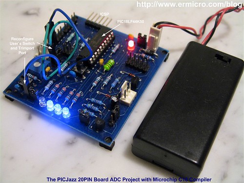
On this tutorial we will learn of how to program the PIC18LF14K50 microcontroller ADC peripheral using the Microchip C18 compiler. The principal we learn here could be applied to the other Microchip PIC18 microcontroller family as well. On this tutorial we will use this following simplify ermicro PICJazz 20PIN board schematic.

After placing the PIC18LF14K50 to the 20 pin socket; using the female to female cable jumper that come with the PICJazz 20PIN board we could easily reconfigure the user trimport and user switch to RA4 and RA5 respectively.

PIC18 Microcontroller Analog to Digital Converter with Microchip C18 Compiler

On this tutorial we will use two different approaches to program the PIC18 microcontroller family analog to digital converter (ADC) peripheral. The first one is to use the standard C programming code to manipulate the PIC18LF14K50 ADC peripheral registers and the second one is to use the Microchip C18 ADC wrap-up library. Now take a look on our first code:

/* *************************************************************************** **  File Name    : adc.c **  Version      : 1.0 **  Description  : Analog to Digital Converter **  Author       : RWB **  Target       : PICJazz 20PIN Board: PIC18LF14K50 **  Compiler     : Microchip C18 v3.34 C Compiler **  IDE          : Microchip MPLAB IDE v8.30 **  Programmer   : Microchip PICKit2 Programmer **  Last Updated : 28 Oct 2009 ** ***************************************************************************/ #include  #include 
/* ** PIC18LF14K50 Configuration Bit: ** ** FOSC = IRC        - Internal RC Oscillator ** CPUDIV = NOCLKDIV - No CPU System Clock divide ** PLLEN = OFF       - PLL is under software control ** FCMEN = OFF       - Fail-Safe Clock Monitor disabled ** BOREN = OFF       - Brown-out Reset disabled in hardware and software ** WDTEN = OFF       - WDT is controlled by SWDTEN bit of the WDTCON register ** MCLRE = ON        - MCLR pin enabled, RE3 input pin disabled ** LVP = OFF         - Single-Supply ICSP disabled */ #pragma config FOSC = IRC, CPUDIV = NOCLKDIV, PLLEN = OFF #pragma config FCMEN = OFF, BOREN = OFF #pragma config WDTEN = OFF, MCLRE = ON, LVP = OFF
// Delay in 1 ms (approximately) for 16 MHz Internal Clock void delay_ms(unsigned int ms) {   do {     Delay1KTCYx(4);   } while(--ms); }
void main(void) {   unsigned char chSign,chEye,chType,iCount;   unsigned int iDelay;   unsigned char led_patern[] = {0b00000000,0b00000001,                                 0b00000011,0b00000111,                                 0b00001111,0b00001111,                                 0b00001110,0b00001100,                                 0b00001000,0b00000000};
  OSCCON=0x70;         // Select 16 MHz internal clock
  TRISC = 0x00;        // Set All on PORTC as Output   TRISA = 0x30;        // Input for RA4 and RA5   ANSEL = 0b00001000;  // Set PORT AN3 to analog input   ANSELH = 0;          // Set PORT AN8 to AN11 as Digital I/O
  /* Init ADC */   ADCON0=0b00001101;   // ADC port channel 3 (AN3), Enable ADC   ADCON1=0b00000000;   // Use Internal Voltage Reference (Vdd and Vss)   ADCON2=0b10101011;   // Right justify result, 12 TAD, Select the FRC for 16 MHz
  chEye=0x01;          // Initial Eye Variables with 0000 0001   chSign=0;   iDelay=100;   chType=0;   iCount=0;    for(;;) {     ADCON0bits.GO=1;     while (ADCON0bits.GO);   // Wait conversion done
    iDelay=ADRESL;           // Get the 8 bit LSB result     iDelay += (ADRESH << 8); // Get the 2 bit MSB result
    // Display the LED     if (PORTAbits.RA5 == 0) {       chType=~chType;       chSign=0;     }
    if (chType == 0) {       PORTC=led_patern[iCount++];       delay_ms(iDelay);          // Call Delay function       if(iCount == 10) iCount=0;     } else {       if (chSign == 0) {  PORTC=chEye;  delay_ms(iDelay);        // Call Delay function  chEye=chEye << 1;    if (chEye > 0x04) chSign=1;       } else {         PORTC=chEye;         delay_ms(iDelay);        // Call Delay function         chEye=chEye >> 1;  if (chEye <= 0x01) chSign=0;       }     }   } }
/* EOF: adc.c */

The Analog to Digital Converter C Code

This program basically will show the running LED pattern attached to RC0, RC1, RC2 and RC3 ports on the PIC18LF14K50 microcontroller; the display speed is controlled by the voltage value reads from the user’s trimport on the port RA4 (AN3 - analog input channel 3). This voltage value will be converted by the PIC18LF14K50 ADC peripheral and passing the converted numeric value as the delay argument on the delay_ms() function inside the loop. Pressing the user’s switch will change the running LED pattern.

The user’s trimport work as the voltage divider circuit and provide voltage input level to the microcontroller analog port (AN3); therefore by changing the trimmer means we change the voltage level input and this also will change the running LED speed.

The user’s switch works as a toggle switch, by pressing it once will switch to the second running LED pattern; pressing once again will switch back to the first running LED pattern.

Just for your reference, you could read of how to program the Microchip PIC16 microcontroller family ADC peripheral using HITEC PICC on my previous posted blog PIC Analog to Digital Converter C Programming. Ok now let’s take a look at the PIC18LF14K50 microcontroller ADC peripheral registers (for more information please refers to the datasheet).

1. ADCON0: A/D CONTROL REGISTER 0

The function of this register is to control the microcontroller ADC operation such as power on the ADC circuit, start converting, channel selection, ADC voltage reference selection and ADC result format presentation selection.

The CHS3, CHS2, CHS1 and CHS0 bits are used to select the ADC input channel, by setting all these bits to “0011” means we choose the channel 3 or AN3 (PIN 3) port which connected to the user’s trimport.

ADCON0=0b00001101;   // ADC port channel 3 (AN3), Enable ADC

Powering the ADC circuit is simply turning on the ADON bit by setting it to logical “1” and to instruct the PIC microcontroller to start the conversion we just turn on the GO/DONE bit (logical “1“) and wait until this bit turn off when the PIC18LF14K50 microcontroller ADC peripheral done with the conversion; we use the C while statement to wait the ADC conversion as this following code:

ADCON0bits.GO=1; while (ADCON0bits.GO);   // Wait conversion done

2. ADCON1: A/D CONTROL REGISTER 1

The PIC18LF14K50 microcontroller ADC peripheral uses the successive approximation method to do the conversion; this method required the reference voltage in order to work. The ADCON1 register is use to tell the ADC peripheral whether we want to use the internal or external voltage references.

By setting all of these bits to logical “0“, we simply tell the PIC18LF44K50 microcontroller ADC peripheral to use its own internal voltage reference for the conversion.

ADCON1=0b00000000;   // Use Internal Voltage Reference (Vdd and Vss)

3. ADCON2: A/D CONTROL REGISTER 2

The ADCON2 register is use to set of how the 10-bit ADC result will be presented in two 8-bit registers (ADRESH and ADRESL) and to select the ADC acquisition time and the ADC conversion clock.

By setting the ADFM bit to logical “1” we use the “right justified” result. This mean the higher 2 bits value will be place in the ADRESH register and the lower 8 bits value are in the ADRESL register. By using the C left shifting operation, we could get this 10-bit value as this following code:

iDelay = ADRESL;           // Get the 8 bit LSB result iDelay += (ADRESH << 8);   // Get the 2 bit MSB result

In order for ADC circuit inside the PIC18LF44K50 microcontroller to meet its specified accuracy than ADC clock period (ADCS) and the ADC acquisition time (ACQT) should be set accordingly

The recommended minimum value for the ADC acquisition time before the ADC circuit start to do the conversion is about 7.45 us and when we use the PIC8LF14K50 microcontroller internal oscillator the time required to convert 1-bit analog data is about 1.7 us; therefore it would be safe to choose twice the minimum acquisition time:

TACQT = 2 x 7.45 us = 14.9 us

The closest ACQT setting for this purpose is to set the ACQT to 12 TAD which give us

TACQT = 12 TAD = 12 x 1.7 us = 20.4 us

If you are not using the TACQT (ACQT2 = 0, ACQT1= 0 and ACQT0 = 0) you have to do the delay in program before starting the AD conversion, therefore it always safer to use the PIC18LF14K50 microcontroller ACQT feature. The following is the complete ADCON2 setup:

ADCON2=0b10101011;   // Right justify result, 12 TAD, Select the FRC for 16 MHz

The PIC18LF14K50 microcontroller ADC peripheral is also capable of generating interrupt when it finish the conversion by setting the ADC interrupt flag ADIF bit to logical “1” in PIR1 register, but for the purpose of this tutorial we will not use this facility.

Initial the Internal Oscillator clock and ADC Port

One of the most important setup before we could use the PIC ADC peripheral is to configure the PIC18LF14K50 microcontroller internal clock and ports.

By setting the IRCF2, IRCF1 and IRCF0 bits to logical “1” on the OSCCON register we choose the 16 MHz internal clock from the high frequency internal oscillator (HFINTOSC):

OSCCON=0x70;         // Select 16 MHz internal clock

For the analog input this can be done by setting the TRISA, ANSEL and ANSELH registers as the following code:

TRISC = 0x00;        // Set All on PORTC as Output TRISA = 0x30;        // Input for RA4 and RA5 ANSEL = 0b00001000;  // Set PORT AN3 to analog input ANSELH = 0;          // Set PORT AN8 to AN11 as Digital I/

Because the we use both RA4 and RA5 ports as an input ports (RA4 for user’s trimport and RA5 for user’s switch) then we turn on the tristate input gate on these ports by setting the TRISA to 0×30 and enabling the AN3 analog input selection by setting the ANSEL to 0b00001000 (0×08 hex value). For the LED’s, we just enabling all of the PORTC tristate gate ports as an output by setting the TRISC register to all zero.

Downloading your C18 ADC project Code

After compiling and simulating your code hook up your PICKit2 programmer to the PICJazz 20PIN board ICSP port turn on the PICJazz 20PIN power. From the MPLAB IDE menu select Programmer -> Select Programmer -> Pickit2 it will automatically configure the connection and display it on the PICkit2 tab Output windows:

You could get the information about the size of your program by opening the adc.map file in your project directory or you could use the MPLAB IDE Memory Usage Gauge facility from the MPLAB IDE menu select View -> Memory Usage Gauge as follow:

Now you are ready to down load the code from MPLAB IDE menu select Programmer -> Program; this will down load the HEX code into the PICJazz 20PIN board:

You could see the running code on the video at the end of this tutorial.

Using the Microchip C18 ADC Peripheral Library

As I mention before that on this tutorial we are going to use the alternative approach to code the PIC18LF14K50 microcontroller ADC peripheral, where we are going to use the Microchip C18 ADC wrap-up library (version 3.34). Using this library supposedly will be much easier than coding the PIC18F14K50 microcontroller ADC peripheral registers directly especially for the beginners; …hmm let’s find out how ease this approach comparing to the first one.

Looking at the Microchip C18 library (MPLAB_C18_Libraries_51297f.pdf) document the ADC library could be used as the above diagram. First we have to use the OpenADC() function to initial the PIC18LF14K50 microcontroller ADC peripheral registers. From the library we know that this function is depend on the microcontroller type we used; therefore to get more detail information about this ADC library we have to read other C18 peripheral library document file found at \doc\periph-lib\AD Converter.htm. From this reference document you will get 12 version of the OpenADC() function and for the PIC18LF14K50 microcontroller we have to use the ADC_V10 OpenADC() function as follow (taken from the AD Converter.htm document):

Function: Configure the A/D convertor. Include: adc.h Prototype:
void OpenADC(unsigned char config,                       unsigned char config2 ,                       unsigned char config3,                       unsigned int portconfig);
Code Example:
With AND mask: OpenADC( ADC_FOSC_32      &          ADC_RIGHT_JUST   &          ADC_12_TAD,          ADC_CH0          &          ADC_REF_VDD_VSS  &          ADC_INT_ON, ADC_10ANA);
With OR mask: OpenADC( ADC_FOSC_32 |          ADC_RIGHT_JUST |          ADC_12_TAD,          ADC_CH0 |          ADC_REF_VDD_VSS |          ADC_INT_ON, ADC_10ANA);

This ADC_V10 OpenADC() function will accept 4 arguments: config, config2, config3 and portconfig; you should remember here for other PIC18 microcontroller type the OpenADC() function version may accept only 2 or 3 arguments instead of 4 arguments therefore its important to know which OpenADC() function to be used when you use the other type of PIC18 microcontroller family. There is no general OpenADC() function that work to all PIC18 microcontroller type.

The ADC_V10 OpenADC() function first argument (config) is used to set the A/D Clock Source, A/D result justification and the A/D acquisition time. The second argument (config2) is used to set the A/D channel, A/D interrupt and some miscellaneous option. The third argument (config3) is used to set the A/D Vref+ and Vref- configuration and last the fourth argument (portconfig) is used to set the analog channel port (i.e. ANSEL and ANSELH registers).

Now we continue to look at the ADC_V10 OpenADC() function code example and you will notice that the example only use 3 arguments instead of 4 arguments? Is this mean that the example document give us a wrong information? Now its time to open the ADC_V10 OpenADC() function wrap-up library to find out how this thing really work. Opening the \src\pmc_common\ADC\adcopen.c file and here what we get for the ADC_V10 OpenADC() function:

#elif defined (ADC_V10) void OpenADC( unsigned char config,               unsigned char config2,               unsigned char config3,               unsigned int portconfig) {     ADCON0 = 0;     ADCON1 = 0;     ADCON2 = 0;
    ADCON0 = (config2 >> 1) & 0b00111100;  //channel selection     ADCON1 = (config3 & 0b00001100) | //Positive Voltage Reference Configuration bits              (config3 & 0b00000011);  //Negative Voltage Reference Configuration bits     ADCON2 = (config & 0b10000000) |              ((config >> 4) & 0b00000111) | //A/D Conversion Clock Select bits              ((config << 2) & 0b00111000);  //A/D Acquisition Time Select bits
    ANSEL = portconfig;   //Didn't Change     ANSELH = (portconfig >> 8);  //Didn't Change   if( config2 & 0b10000000 )  //interrupt enable check     {       PIR1bits.ADIF = 0;   //Clear the ADC Interrupt bit       PIE1bits.ADIE = 1;   //Enable the ADC Interrupt       INTCONbits.PEIE = 1;   //Peripheral Interrupt Enable     }     //A/D Conversion Status bit--A/D converter module is operating     ADCON0bits.ADON = 1; }

Hmm,.. this ADC_V10 OpenADC() function use 4 arguments after all (the example document is wrong) and this code seem similar to what we have already done on the first example; by carefully reading the necessary bits definition in the \h\adc.h file and used them with the AND mask as the arguments to the ADC_V10 OpenADC() function; do some debugging on the required PIC18LF14K50 registers, finally I came with this following C code:

/* *************************************************************************** **  File Name    : adc2.c **  Version      : 1.1 **  Description  : Analog to Digital Converter **                 Using C18 ADC Peripheral Wrap-up Library **  Author       : RWB **  Target       : PICJazz 20PIN Board: PIC18LF14K50 **  Compiler     : Microchip C18 v3.34 C Compiler **  IDE          : Microchip MPLAB IDE v8.30 **  Programmer   : PICKit2 **  Last Updated : 28 Oct 2009 ** ***************************************************************************/ #include  #include  #include 
/* ** PIC18LF14K50 Configuration Bit: ** ** FOSC = IRC        - Internal RC Oscillator ** CPUDIV = NOCLKDIV - No CPU System Clock divide ** PLLEN = OFF       - PLL is under software control ** FCMEN = OFF       - Fail-Safe Clock Monitor disabled ** BOREN = OFF       - Brown-out Reset disabled in hardware and software ** WDTEN = OFF       - WDT is controlled by SWDTEN bit of the WDTCON register ** MCLRE = ON        - MCLR pin enabled, RE3 input pin disabled ** LVP = OFF         - Single-Supply ICSP disabled */ #pragma config FOSC = IRC, CPUDIV = NOCLKDIV, PLLEN = OFF #pragma config FCMEN = OFF, BOREN = OFF #pragma config WDTEN = OFF, MCLRE = ON, LVP = OFF
// Delay in ms (approximately) for 16 MHz Internal Clock void delay_ms(unsigned int ms) {   do {     Delay1KTCYx(4);   } while(--ms); }
void main(void) {   unsigned char chSign,chEye,chType,iCount;   unsigned int iDelay;   unsigned char led_patern[] = {0b00000000,0b00000001,                                 0b00000011,0b00000111,                                 0b00001111,0b00001111,                                 0b00001110,0b00001100,                                 0b00001000,0b00000000};
  OSCCON=0x70;         // Select 16 MHz internal clock
  TRISC = 0x00;        // Set All on PORTC as Output   TRISA = 0x30;        // Input for RA4 and RA5      /* Init ADC */   /*   ** Original:   ** #define ADC_REF_VDD_VDD 0b11111001 // ADC voltage source VREF+ = AVDD   **   ** We redefine this definition to ADC_REF_VDD_VDD_X   */   #define ADC_REF_VDD_VDD_X 0b11110011  // ADC voltage source VREF+ = AVDD
  OpenADC(ADC_FOSC_RC & ADC_RIGHT_JUST & ADC_12_TAD,           ADC_CH3 & ADC_INT_OFF,           ADC_REF_VDD_VDD_X & ADC_REF_VDD_VSS,           0b00001000);
  chEye=0x01;          // Initial Eye Variables with 0000 0001   chSign=0;   iDelay=100;   chType=0;   iCount=0;      for(;;) {     ConvertADC();                 // Start conversion     while(BusyADC());             // Wait for completion     iDelay = ReadADC();           // Read result      // Display the LED     if (PORTAbits.RA5 == 0) {       chType=~chType;       chSign=0;     }
    if (chType == 0) {       PORTC=led_patern[iCount++];       delay_ms(iDelay);           // Call Delay function       if(iCount == 10) iCount=0;     } else {       if (chSign == 0) {  PORTC=chEye;  delay_ms(iDelay);         // Call Delay function  chEye=chEye << 1;    if (chEye > 0x04) chSign=1;       } else {         PORTC=chEye;         delay_ms(iDelay);         // Call Delay function         chEye=chEye >> 1;  if (chEye <= 0x01) chSign=0;       }     }   }   CloseADC(); // Disable A/D converter }
/* EOF: adc2.c */

As you’ve seen from the above code, I had to redefine the third argument definition ADC_REF_VDD_VDD (0b11111001) to ADC_REF_VDD_VDD_X (0b11110011) to make the ADC_V10 OpenADC() function to set the PIC18LF14K50 microcontroller ADCON1 register correctly (using the internal voltage reference). I think this is a bug for the ADC_V10 type on the Microchip C18 version 3.34 ADC peripheral libraries.

For starting and reading the ADC channel using this library is just a little bit easier comparing to the first approach as shown on this following code:

ConvertADC();                 // Start conversion while(BusyADC());             // Wait for completion iDelay = ReadADC();           // Read result

Just for curiosity, I put this following memory usage gauge to compare the memory usage between using the Microchip C18 ADC peripheral library approach and without using it; and it’s obvious that using the first approach give you a lesser HEX code size.

After compiling and downloading the HEX code to the PICJazz 20PIN board you will have similar result as shown on this following video:

The Final Though

Is obviously the Microchip C18 (version 3.34) ADC peripheral library is not ease to use at all and certainly is not intended to be used by the beginners; as you will have to read many documents and must have a good understanding of the PIC18 microcontroller ADC principal in order to make this library work for you. My suggestion is to avoid using the Microchip C18 ADC peripheral library (especially if you are really not understand the PIC18 microcontroller ADC peripheral) and use direct register manipulation as shown on the first approach to handle your PIC18 microcontroller ADC project.

Sunday, July 3, 2011

vb6

Latest VB6 Tutorials

Level:
Level2

Creating PDF files in Visual Basic

Creating PDF documents in Visual Basic has always been a difficult task. Many times people have to purchase controls to do it for them. Not with this Visual Basic tutorial. PDF documents can be created in a snap using the mjwPDF class. This is the first in a series of tutorials. It covers the creation of a basic PDF document.
Level:
Level3

Creating Advanced PDF documents in VB

This VB tutorial builds off the last and demonstrates how you can create more advanced PDF files. It teaches you how to create a multi-page document, with page headers, footers, page numbers, shapes, and images.
Level:
Level2

Visual Basic 6 String Functions

This tutorial explains all the main vb6 string functions that allow you to manipulate strings including the Len, Mid, Left, Right, UCase, LCase, Instr, InstrRev, String, Space, Replace, StrReverse, LTrim, RTrim, Trim, Asc, Chr, and the ASCII table. This Visual Basic tutorial should meet all your needs.
Level:
Level2

Date Time Functions In Visual Basic

Learn how to use the time and date functions in Visual Basic. This VB6 tutorial introduces you to the basics of these functions.
Level:
Level2

Visual Basic Combo Box Tutorial

Visual Basic combo boxes are like list boxes but they allow you to have a drop down list and/or be able to type in your own list items instead of only selecting one of the current items. This VB6 combo box tutorial teaches you everything you need to know to use combo boxes in your Visual Basic application.
Level:
Level2

Visual Basic & ADO Tutorial

This VB6 tutorial explains how to access a database using ADO in. It uses two different access databases for the back end.
Level:
Level2

Using Crystal Reports

Learn how to use Crystal Reports to display a nice report from your database in.
Level:
Level2

Database Access with the Data Control

See examples of developing database applications using the data control that ships with Visual Basic 6.
Level:
Level2

VB6 Downloads

Want to get a hold of Visual Basic 6.0? Do you have a program written in VB that you wish to run but don't have the VB6 runtime any longer? Have an older program and want to get it running on the latest OS. Read this article for information about downloading VB6 and other VB components.
Level:
Level3

Amazing things you can do with the Listbox control

Learn everything about the Listbox control. From simple to advanced to very advanced things you can do with this neat control.
Level:
Level1

How to read simple text files

This tutorial explains in detail how you can open text files in different formats and read them into your Visual Basic program.
Level:
Level1

Understanding the MsgBox command in Visual Basic

This Visual Basic tutorial explains everything you need to know about displaying a message box using the VB6 MsgBox command.
Level:
Level2

VB String Array Functions - Split, Join, Filter

Visual Basic has a few built in string array functions including Split, Join, and Filter. This VB tutorial explains how to use them.
Level:
Level2

Using ADO and the ListView control

See how to create a program that reads data using ADO and displays it in a nice ListView control in this VB6 tutorial.
Level:
Level1

Understanding the timer control

The timer control is very useful learn how to use it effectively.
Level:
Level1

Understanding Forms and form events

This explains in detail how forms work in Visual Basic. It demonstrates how to create them and handle events.
Level:
Level3

Using ADO and stored procedures

Learn how to use ADO along with stored procedures in this VB6 tutorial. It shows examples using an access database, SQL database, and oracle database.
Level:
Level1

Understanding For, Do, and while Loops

This tutorial explains all of the Visual Basic 6 loop commands (the do loop, do-while loop, do-until loop, and for loop) all with code to demonstrate.
Level:
Level2

Working with images in all different ways

Learn many different ways to work with images in - such as resizing them, displaying them, using icons, etc.
Level:
Level1

Formating dates and times in VB6

This VB6 tutorial explains how you can format dates and times using the Visual Basic format command.
Level:
Level3

Introduction to SQL (Structured Query Language)

This explains in great depth how the SQL language works. It has many examples and uses access databases to demonstrate the SQL syntax.
Level:
Level1

Using Option Buttons aka Radio Buttons

Learn how to use the option buttons aka radio button controls in your Graphical User Interface (GUI).
Level:
Level3

Using DAO (Data Access Objects) Code

This demonstrates a full working application using nothing but DAO code (no data control) this gives you the advantage of having full control over everything.
Level:
Level2

Working with Menus in VB6

This tutorial explains how you can work with Menus in Visual Basic. It covers both normal (on the top) menus and pop-up menus (that "popup" when you right click). You will use both these types of menu's in almost any Visual Basic application you develop.
Level:
Level1

Beginner Tutorial - Hello World

Create your first working application that says "Hello, World!". A standard in all programming environments.
Level:
Level1

Understanding control arrays

This explains the very useful feature of control arrays. Control arrays allow you to create controls at runtime.
Level:
Level2

Multiple Form Splash Screen

Learn how you can use multiple forms. This example shows how to display a splash screen to your program before it starts.
Level:
Level2

Database Access with RDO (Remote Data Objects)

This demonstrates how you can use RDO (remote data objects) in Visual Basic to access a database.
Level:
Level1

Getting to know the VB6 IDE

This tutorial helps the beginner (and even more experienced users) understand a lot of the cool features the VB6 environment has to offer.
Level:
Level2

A Client server Chat program using the Winsock control

See how easy it is to create a simple chat program. This tutorial explains how to create both the client and server sides of the program using the Winsock control.

Latest VB6 Source Code Samples

Level:
Level1

Use API To See If Windows Started In Safe Mode

You can interact with any built in Windows API function from Visual Basic. This source sample shows how we can use the GetSystemMetrics API function in order to find out if Windows was started in safe mode or not.
Level:
Level1

Drag and Drop With List Box

Drag and Drop is cool and very useful feature that any modern application must implement. This sample demonstrates how you can allow users to drag files from explorer onto a listbox.
Level:
Level1

Simple way to store strings in the Registry

The Windows Registry is a great place to store program settings. Visual basic has SaveSettings and GetSettings functions to be able to easily store and retrieve data from the registry.
Level:
Level1

Convert HTML Color to RGB

In this day and age you will find yourself needing to convert colors that are specified in the format for websites into RGB colors that can be used in your VB programs. This is easy to do with this very simple code snippet.
Level:
Level1

Fancy Collapsing Form Exit

New VB developers quickly learn how to Unload their forms. This source code snippet shows you how you can add a little style to your form unloading event. Instead of just making it disappear the form will shrink into non-existence.
Level:
Level1

Replace Text in a TextBox

Many people have seen the Find and Replace functionality in Word or other applications. You can implement similar functionality in your VB programs with just a few lines of code.
Level:
Level1

Count the number of words in a textbox

At times we want to say that so many words can or must be entered in a text box field. Getting the character count of a field is easy in Visual Basic, but getting the word count takes a little more work. This source code shows you how to calculate this word count.
Level:
Level1

Remove an element from an array

Visual Basic Arrays are very handy and at times somewhat complicated, especially if you want to remove an item from it or redefine its size. This VB sample shows you how to do this.
Level:
Level1

Save the contents of a list box to a file

Controls in VB are very handy. However, none of them have built in methods to save their contents out to the hard drive. This source sample shows you exactly how to take all the items in a list and save them into a text file you specify.
Level:
Level1

Copy a File Quickly

Visual Basic can be used for lower level functionality such as copying all the data from one file into another one. This source code sample shows you how to do this using the Open, Get, Put, and Close File IO Functions.
Level:
Level1

Print 3D Gradiant text on a form

This is a simple and fun example of a cool effect you can do in VB - Setting the forms background to a gradiant of color. It also showcases how you can use the VB6 For loop.
Level:
Level1

Fill a combo box with system fonts

Every Window's system has a bunch of fonts installed on it that we can use to display text in different ways. This sample shows how we can use Visual Basic's Screen object to query these fonts and list them all in a combo box.
Level:
Level1

Launch a program from VB

A fun thing to develop when you are first learning how to program is a program launcher. This sample source code shows you how you can use VB's built in shell command in order to launch other programs from within your custom application.
Level:
Level1

Center your form on the screen

Visual Basic gives us access to the Screen object in order to find out information about the end users screen resolution and other settings. We can use this in order to make our form appear in the center of the screen. This sample source code shows you how.
Level:
Level1

Get tag info form a mp3 file

MP3 files are common place now days. When Visual Basic 6.0 first came out MP3 files weren't even used. However, you can still use VB6 to read all the tag information of this song files.
Level:
Level1

A very basic web server Test

Writing network related programs is fun and exciting. At times it almost seems like magic. This source code sample shows how you can create a very basic web server that when your browser connects to it the specified text will show up in the browser. This uses the Microsoft Winsock control.
Level:
Level1

Looping through files and putting them in a control

See an example of how you can interact with the system to find out all files in a given folder. Further add all these files (and their paths) to a listbox control.
Level:
Level1

Delete A File - Snippet

Learn in this simple source code snippet exactly how you can delete a file from your computer using Visual Basic. It is a very simple example to showcase the Kill command in VB.
Level:
Level1

Tile A Picture - Quick Source

A simple source snippet that shows how you can tile any image both horizontally and vertically on a VB form.
Level:
Level2

Create PDF in VB Source Code

This sample source code shows you exactly how to create a PDF file from within your VB application with out having to buy a third party control or dll. It gives an example of creating a PDF and adding text to it.